skip to main |
skip to sidebar
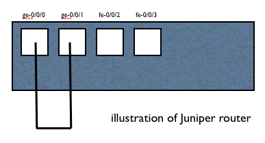
The mini lab Juniper is template topology and preconfig to test, verify feature or behaviour. This mini lab are contain several router and connected each other. The lab is using one physical router and create several virtual-router. Each virtual-router looks like as logical router, due to virtual-router can separate routing table.
From today and next I will use this mini lab for topology and preconfig.
Please find the parameter, topology and configuration
####
# Project name: Juniper Mini Lab with Virtual-Router
# Version: 1.0
# Code name: JMib_VR
# Short name: JMib_VR_v1.0
# Release date: 2013/10/20
####
#### The Parameter
# R1
- lt-0/0/0.14 172.16.14.1/24
- lt-0/0/0.15 172.16.15.1/24
# R2
- lt-0/0/0.23 172.16.23.2/24
- lt-0/0/0.24 172.16.24.2/24
# R3
- lt-0/0/0.32 172.16.23.3/24
- lt-0/0/0.35 172.16.35.3/24
# R4
- lt-0/0/0.41 172.16.14.4/24
- lt-0/0/0.42 172.16.24.4/24
# R5
- lt-0/0/0.51 172.16.15.5/24
- lt-0/0/0.53 172.16.35.5/24
#### The Topology
R1 -- R4 -- R2 -- R3
R1 -- R5 -------- R3
#### Configuration
## R1 -- R4
set interfaces lt-0/0/0 unit 14 description "R1.R4"
set interfaces lt-0/0/0 unit 14 encapsulation ethernet
set interfaces lt-0/0/0 unit 14 peer-unit 41
set interfaces lt-0/0/0 unit 14 family inet address 172.16.14.1/24
set interfaces lt-0/0/0 unit 41 description "R1.R4"
set interfaces lt-0/0/0 unit 41 encapsulation ethernet
set interfaces lt-0/0/0 unit 41 peer-unit 14
set interfaces lt-0/0/0 unit 41 family inet address 172.16.14.4/24
set routing-instances R1 instance-type virtual-router
set routing-instances R1 interface lt-0/0/0.14
set routing-instances R4 instance-type virtual-router
set routing-instances R4 interface lt-0/0/0.41
## R1 -- R5
set interfaces lt-0/0/0 unit 15 description "R1.R5"
set interfaces lt-0/0/0 unit 15 encapsulation ethernet
set interfaces lt-0/0/0 unit 15 peer-unit 51
set interfaces lt-0/0/0 unit 15 family inet address 172.16.15.1/24
set interfaces lt-0/0/0 unit 51 description "R1.R5"
set interfaces lt-0/0/0 unit 51 encapsulation ethernet
set interfaces lt-0/0/0 unit 51 peer-unit 15
set interfaces lt-0/0/0 unit 51 family inet address 172.16.15.5/24
set routing-instances R1 instance-type virtual-router
set routing-instances R1 interface lt-0/0/0.15
set routing-instances R5 instance-type virtual-router
set routing-instances R5 interface lt-0/0/0.51
## R2 -- R3
set interfaces lt-0/0/0 unit 23 description "R2.R3"
set interfaces lt-0/0/0 unit 23 encapsulation ethernet
set interfaces lt-0/0/0 unit 23 peer-unit 32
set interfaces lt-0/0/0 unit 23 family inet address 172.16.23.2/24
set interfaces lt-0/0/0 unit 32 description "R2.R3"
set interfaces lt-0/0/0 unit 32 encapsulation ethernet
set interfaces lt-0/0/0 unit 32 peer-unit 23
set interfaces lt-0/0/0 unit 32 family inet address 172.16.23.3/24
set routing-instances R2 instance-type virtual-router
set routing-instances R2 interface lt-0/0/0.23
set routing-instances R3 instance-type virtual-router
set routing-instances R3 interface lt-0/0/0.32
## R2 -- R4
set interfaces lt-0/0/0 unit 24 description "R2.R4"
set interfaces lt-0/0/0 unit 24 encapsulation ethernet
set interfaces lt-0/0/0 unit 24 peer-unit 42
set interfaces lt-0/0/0 unit 24 family inet address 172.16.24.2/24
set interfaces lt-0/0/0 unit 42 description "R2.R4"
set interfaces lt-0/0/0 unit 42 encapsulation ethernet
set interfaces lt-0/0/0 unit 42 peer-unit 24
set interfaces lt-0/0/0 unit 42 family inet address 172.16.24.4/24
set routing-instances R2 instance-type virtual-router
set routing-instances R2 interface lt-0/0/0.24
set routing-instances R4 instance-type virtual-router
set routing-instances R4 interface lt-0/0/0.42
## R3 -- R5
set interfaces lt-0/0/0 unit 35 description "R3.R5"
set interfaces lt-0/0/0 unit 35 encapsulation ethernet
set interfaces lt-0/0/0 unit 35 peer-unit 53
set interfaces lt-0/0/0 unit 35 family inet address 172.16.35.3/24
set interfaces lt-0/0/0 unit 53 description "R5.R3"
set interfaces lt-0/0/0 unit 53 encapsulation ethernet
set interfaces lt-0/0/0 unit 53 peer-unit 35
set interfaces lt-0/0/0 unit 53 family inet address 172.16.35.5/24
set routing-instances R3 instance-type virtual-router
set routing-instances R3 interface lt-0/0/0.35
set routing-instances R5 instance-type virtual-router
set routing-instances R5 interface lt-0/0/0.53
#### Verify
user@JunOS> #### Verify
user@JunOS> ping routing-instance R1 172.16.14.4 source 172.16.14.1 rapid
PING 172.16.14.4 (172.16.14.4): 56 data bytes
!!!!!
--- 172.16.14.4 ping statistics ---
5 packets transmitted, 5 packets received, 0% packet loss
round-trip min/avg/max/stddev = 2.691/3.303/4.401/0.595 ms
user@JunOS> ping routing-instance R1 172.16.15.5 source 172.16.15.1 rapid
PING 172.16.15.5 (172.16.15.5): 56 data bytes
!!!!!
--- 172.16.15.5 ping statistics ---
5 packets transmitted, 5 packets received, 0% packet loss
round-trip min/avg/max/stddev = 2.730/3.104/3.690/0.335 ms
user@JunOS> ping routing-instance R2 172.16.23.3 source 172.16.23.2 rapid
PING 172.16.23.3 (172.16.23.3): 56 data bytes
!!!!!
--- 172.16.23.3 ping statistics ---
5 packets transmitted, 5 packets received, 0% packet loss
round-trip min/avg/max/stddev = 2.805/5.181/8.782/2.746 ms
user@JunOS> ping routing-instance R2 172.16.24.4 source 172.16.24.2 rapid
PING 172.16.24.4 (172.16.24.4): 56 data bytes
!!!!!
--- 172.16.24.4 ping statistics ---
5 packets transmitted, 5 packets received, 0% packet loss
round-trip min/avg/max/stddev = 2.739/3.290/3.986/0.424 ms
user@JunOS> ping routing-instance R3 172.16.35.5 source 172.16.35.3 rapid
PING 172.16.35.5 (172.16.35.5): 56 data bytes
!!!!!
--- 172.16.35.5 ping statistics ---
5 packets transmitted, 5 packets received, 0% packet loss
round-trip min/avg/max/stddev = 2.495/2.997/3.329/0.308 ms
I just little add for previous posting about Firewall Juniper SRX Implicit Deny. Sometime you rush to configure the SRX and forget to add policy permit in security zone. Lets remember again about OSI 7 layer and zoom in layer 2, layer 3 and layer 4 if working with firewall.
The scenario is JunOSRX (192.168.1.1/24) and XYZ server (192.168.1.11/24)
#### Layer 1 Connect physical cable between JunOSRX and XYZ
#### Layer 2 Check mac address XYZ in JunOSRX
#### If we can see XYZ mac address, it's mean Layer 1 and layer 2 is pass
user@JunOSRX> show arp
MAC Address Address Name Interface Flags
aa:bb:cc:dd:ee:01 192.168.1.11 192.168.1.11 ge-0/0/1.0 none
Total entries: 1
#### Layer 3 for XYZ in JunOSRX
user@JunOSRX> show configuration interfaces ge-0/0/1
unit 0 {
description "to XYZ";
family inet {
address 192.168.1.1/24;
}
}
#### Sometime for fast, we skip check/define layer 4 and continue to check application layer with ping
#### Remember again, If play with firewall, layer 2, layer 3 and layer 4 should be pass
#### Verify Application Layer
user@JunOSRX> ping 192.168.1.11 source 192.168.1.1 rapid
PING 192.168.1.11 (192.168.1.11): 56 data bytes
.....
--- 192.168.1.11 ping statistics ---
5 packets transmitted, 0 packets received, 100% packet loss
#### Layer 4 Define Firewall Security/Rule/Policy
user@JunOSRX# show security zones security-zone TrustServer
interfaces {
ge-0/0/1.0 {
host-inbound-traffic {
system-services {
all;
}
protocols {
all;
}
}
}
}
#### Repeat verify Application Layer
user@JunOSRX> ping 192.168.1.11 source 192.168.1.1 rapid
PING 192.168.1.11 (192.168.1.11): 56 data bytes
!!!!!
--- 192.168.1.11 ping statistics ---
5 packets transmitted, 5 packets received, 0% packet loss
round-trip min/avg/max/stddev = 3.002/3.867/4.676/0.686 ms
The summary of Juniper Virtual-Router are confirm can run dynamic routing-protocols, OSPF, BGP and packet capture between them use 'monitor traffic'. Communication between Virtual-Router use physical cable loop (jumper). There are a few different way to leak traffic between Virtual-Router logically. The one of them is logical tunnel interface, LT need little config to connect between Virtual-Router.
Please find the example logical tunnel interface, Please check also mini Lab OSPF use physical cable between them, I will add logical interface with that config as pre-config.
#### Create Logical Tunnel Interface
set interfaces lt-0/0/0 unit 10 description "to R1 lt-0/0/0.11 logical tunnel"
set interfaces lt-0/0/0 unit 10 encapsulation ethernet
set interfaces lt-0/0/0 unit 10 peer-unit 11
set interfaces lt-0/0/0 unit 10 family inet address 172.16.11.10/24
set interfaces lt-0/0/0 unit 11 description "to R0 lt-0/0/0.10 logical tunnel"
set interfaces lt-0/0/0 unit 11 encapsulation ethernet
set interfaces lt-0/0/0 unit 11 peer-unit 10
set interfaces lt-0/0/0 unit 11 family inet address 172.16.11.11/24
#### R0
set routing-instances R0 interface lt-0/0/0.10
#### R1
set routing-instances R1 interface lt-0/0/0.11
#### Verify and Ping Test
user@JunOS> ping routing-instance R0 172.16.11.11 source 172.16.11.10 rapid
PING 172.16.11.11 (172.16.11.11): 56 data bytes
!!!!!
--- 172.16.11.11 ping statistics ---
5 packets transmitted, 5 packets received, 0% packet loss
round-trip min/avg/max/stddev = 3.002/3.867/4.676/0.686 ms
user@JunOS> ping routing-instance R1 172.16.11.10 source 172.16.11.11 rapid
PING 172.16.11.10 (172.16.11.10): 56 data bytes
!!!!!
--- 172.16.11.10 ping statistics ---
5 packets transmitted, 5 packets received, 0% packet loss
round-trip min/avg/max/stddev = 3.088/5.639/9.520/2.867 ms
user@JunOS> show arp
MAC Address Address Name Interface Flags
b0:c6:9a:xx:yy:00 172.16.1.10 172.16.1.10 ge-0/0/1.0 none
b0:c6:9a:xx:yy:01 172.16.1.11 172.16.1.11 ge-0/0/0.0 none
b0:c6:9a:xx:yy:00 172.16.11.10 172.16.11.10 lt-0/0/0.11 none
b0:c6:9a:xx:yy:01 172.16.11.11 172.16.11.11 lt-0/0/0.10 none
Total entries: 4
What's next ?
I will join new interface to OSPF instance.
Please stay tune :-)
#### OSPF between R0 and R1
user@JunOS> edit
Entering configuration mode
[edit]
user@JunOS# set routing-instances R0 protocols ospf area 0.0.0.0 interface lt-0/0/0.10
[edit]
user@JunOS# set routing-instances R1 protocols ospf area 0.0.0.0 interface lt-0/0/0.11
[edit]
user@JunOS# show | compare
[edit routing-instances R0 protocols ospf area 0.0.0.0]
interface ge-0/0/0.0 { ... }
+ interface lt-0/0/0.10;
[edit routing-instances R1 protocols ospf area 0.0.0.0]
interface ge-0/0/1.0 { ... }
+ interface lt-0/0/0.11;
[edit]
user@JunOS# commit
commit complete
[edit]
user@JunOS#
#### Verify OSPF
user@JunOS> show ospf neighbor instance all
Instance: R0
Address Interface State ID Pri Dead
172.16.1.11 ge-0/0/0.0 Full 172.16.1.11 128 39
172.16.11.11 lt-0/0/0.10 Full 172.16.1.11 128 36
Instance: R1
Address Interface State ID Pri Dead
172.16.1.10 ge-0/0/1.0 Full 172.16.1.10 128 31
172.16.11.10 lt-0/0/0.11 Full 172.16.1.10 128 37
user@JunOS> show ospf interface instance R0 detail
Interface State Area DR ID BDR ID Nbrs
ge-0/0/0.0 BDR 0.0.0.0 172.16.1.11 172.16.1.10 1
Type: LAN, Address: 172.16.1.10, Mask: 255.255.255.0, MTU: 1500, Cost: 1
DR addr: 172.16.1.11, BDR addr: 172.16.1.10, Priority: 128
Adj count: 1
Hello: 10, Dead: 40, ReXmit: 5, Not Stub
Auth type: None
Protection type: None
Topology default (ID 0) -> Cost: 0
lt-0/0/0.10 BDR 0.0.0.0 172.16.1.11 172.16.1.10 1
Type: LAN, Address: 172.16.11.10, Mask: 255.255.255.0, MTU: 1500, Cost: 1
DR addr: 172.16.11.11, BDR addr: 172.16.11.10, Priority: 128
Adj count: 1
Hello: 10, Dead: 40, ReXmit: 5, Not Stub
Auth type: None
Protection type: None
Topology default (ID 0) -> Cost: 0
user@JunOS> show ospf interface instance R1 detail
Interface State Area DR ID BDR ID Nbrs
ge-0/0/1.0 DR 0.0.0.0 172.16.1.11 172.16.1.10 1
Type: LAN, Address: 172.16.1.11, Mask: 255.255.255.0, MTU: 1500, Cost: 1
DR addr: 172.16.1.11, BDR addr: 172.16.1.10, Priority: 128
Adj count: 1
Hello: 10, Dead: 40, ReXmit: 5, Not Stub
Auth type: None
Protection type: None
Topology default (ID 0) -> Cost: 0
lt-0/0/0.11 DR 0.0.0.0 172.16.1.11 172.16.1.10 1
Type: LAN, Address: 172.16.11.11, Mask: 255.255.255.0, MTU: 1500, Cost: 1
DR addr: 172.16.11.11, BDR addr: 172.16.11.10, Priority: 128
Adj count: 1
Hello: 10, Dead: 40, ReXmit: 5, Not Stub
Auth type: None
Protection type: None
Topology default (ID 0) -> Cost: 0
Previous posted about setup mini lab OSPF with one Juniper use virtual-router to separate route table. The virtual-router is not just separate routing table as basic function, but some of other feature can also separated. It's not just OSPF can run between virtual-router, BGP routing protocols can running well. This is great feature, why ? because a physical router can setup multiple AS number to running multiple BGP process.
The other great way from JunOS to really separation is Logical-Systems (LSYS). LSYS isn't just traffic separation and some feature, but LSYS can administrative separation, logging separation and resource separation. The purpose is to partition system, the system don't talk each other. Special for SRX system, LSYS only allow for the high end SRX (SRX1400, SRX3400, SRX3600, SRX5600 and SRX5800) and also have licenses.
#### R0
user@JunOS> show configuration routing-instances R0
instance-type virtual-router;
interface ge-0/0/0.0;
routing-options {
autonomous-system 10;
}
protocols {
bgp {
group BGPtoR1 {
type external;
peer-as 11;
neighbor 172.16.1.11;
}
}
}
#### R1
user@JunOS> show configuration routing-instances R1
instance-type virtual-router;
interface ge-0/0/1.0;
routing-options {
autonomous-system 11;
}
protocols {
bgp {
group BGPtoR0 {
type external;
peer-as 10;
neighbor 172.16.1.10;
}
}
}
#### Verify BGP
user@JunOS> show bgp summary
Groups: 2 Peers: 2 Down peers: 0
Peer AS InPkt OutPkt OutQ Flaps Last Up/Dwn State|#Active/Received/Accepted/Damped...
172.16.1.10 10 14 15 0 0 5:20 Establ
R1.inet.0: 0/0/0/0
172.16.1.11 11 14 14 0 0 5:20 Establ
R0.inet.0: 0/0/0/0
user@JunOS> show bgp neighbor instance R0 | no-more
Peer: 172.16.1.11+179 AS 11 Local: 172.16.1.10+51682 AS 10
Type: External State: Established Flags:
Last State: OpenConfirm Last Event: RecvKeepAlive
Last Error: None
Options:
Holdtime: 90 Preference: 170
Number of flaps: 0
Peer ID: 172.16.1.11 Local ID: 172.16.1.10 Active Holdtime: 90
Keepalive Interval: 30 Peer index: 0
BFD: disabled, down
Local Interface: ge-0/0/0.0
NLRI for restart configured on peer: inet-unicast
NLRI advertised by peer: inet-unicast
NLRI for this session: inet-unicast
Peer supports Refresh capability (2)
Restart time configured on the peer: 120
Stale routes from peer are kept for: 300
Restart time requested by this peer: 120
NLRI that peer supports restart for: inet-unicast
NLRI that restart is negotiated for: inet-unicast
NLRI of received end-of-rib markers: inet-unicast
NLRI of all end-of-rib markers sent: inet-unicast
Peer supports 4 byte AS extension (peer-as 11)
Table R0.inet.0 Bit: 10000
RIB State: BGP restart is complete
RIB State: VPN restart is complete
Send state: in sync
Active prefixes: 0
Received prefixes: 0
Accepted prefixes: 0
Suppressed due to damping: 0
Advertised prefixes: 0
Last traffic (seconds): Received 8 Sent 17 Checked 24
Input messages: Total 15 Updates 1 Refreshes 0 Octets 289
Output messages: Total 15 Updates 0 Refreshes 0 Octets 348
Output Queue[0]: 0
user@JunOS> show bgp neighbor instance R1 | no-more
Peer: 172.16.1.10+51682 AS 10 Local: 172.16.1.11+179 AS 11
Type: External State: Established Flags:
Last State: OpenConfirm Last Event: RecvKeepAlive
Last Error: None
Options:
Holdtime: 90 Preference: 170
Number of flaps: 0
Peer ID: 172.16.1.10 Local ID: 172.16.1.11 Active Holdtime: 90
Keepalive Interval: 30 Peer index: 0
BFD: disabled, down
Local Interface: ge-0/0/1.0
NLRI for restart configured on peer: inet-unicast
NLRI advertised by peer: inet-unicast
NLRI for this session: inet-unicast
Peer supports Refresh capability (2)
Restart time configured on the peer: 120
Stale routes from peer are kept for: 300
Restart time requested by this peer: 120
NLRI that peer supports restart for: inet-unicast
NLRI that restart is negotiated for: inet-unicast
NLRI of received end-of-rib markers: inet-unicast
NLRI of all end-of-rib markers sent: inet-unicast
Peer supports 4 byte AS extension (peer-as 10)
Table R1.inet.0 Bit: 20000
RIB State: BGP restart is complete
RIB State: VPN restart is complete
Send state: in sync
Active prefixes: 0
Received prefixes: 0
Accepted prefixes: 0
Suppressed due to damping: 0
Advertised prefixes: 0
Last traffic (seconds): Received 21 Sent 12 Checked 12
Input messages: Total 15 Updates 1 Refreshes 0 Octets 329
Output messages: Total 16 Updates 0 Refreshes 0 Octets 367
Output Queue[1]: 0
Then after the BGP established, I will disable interface in R0 ge-0/0/0.0 then enable again. During enable interface ge-0/0/0.0 also capture traffic in R1 ge-0/0/1.0 use internal feature 'monitor traffic'.
#### Verify BGP Packet Capture
user@JunOS> monitor traffic interface ge-0/0/1
verbose output suppressed, use or for full protocol decode
Address resolution is ON. Use to avoid any reverse lookup delay.
Address resolution timeout is 4s.
Listening on ge-0/0/1, capture size 96 bytes
Reverse lookup for 172.16.1.11 failed (check DNS reachability).
Other reverse lookup failures will not be reported.
Use to avoid reverse lookups on IP addresses.
08:46:01.819936 Out IP truncated-ip - 4 bytes missing! 172.16.1.11.58976 > 172.16.1.10.bgp: S 1242851017:1242851017(0) win 16384
08:46:04.922312 Out IP truncated-ip - 4 bytes missing! 172.16.1.11.58976 > 172.16.1.10.bgp: S 1242851017:1242851017(0) win 16384
08:46:06.452115 In IP 172.16.1.10.51682 > 172.16.1.11.bgp: FP 3682718233:3682718254(21) ack 1992165605 win 16384 : BGP, length: 21
08:46:06.452337 Out IP 172.16.1.11.bgp > 172.16.1.10.51682: R 1992165605:1992165605(0) win 0
08:46:08.205122 Out IP truncated-ip - 4 bytes missing! 172.16.1.11.58976 > 172.16.1.10.bgp: S 1242851017:1242851017(0) win 16384
08:46:08.208571 In IP 172.16.1.10.bgp > 172.16.1.11.58976: S 376449534:376449534(0) ack 1242851018 win 16384
08:46:08.208894 Out IP 172.16.1.11.58976 > 172.16.1.10.bgp: . ack 1 win 17376
08:46:08.209875 Out IP truncated-ip - 51 bytes missing! 172.16.1.11.58976 > 172.16.1.10.bgp: P 1:60(59) ack 1 win 17376 : BGP, length: 59
08:46:08.217495 In IP 172.16.1.10.bgp > 172.16.1.11.58976: P 1:60(59) ack 60 win 16384 : BGP, length: 59
08:46:08.218170 Out IP truncated-ip - 11 bytes missing! 172.16.1.11.58976 > 172.16.1.10.bgp: P 60:79(19) ack 60 win 17317 : BGP, length: 19
08:46:08.238541 In IP 172.16.1.10.bgp > 172.16.1.11.58976: P 60:79(19) ack 79 win 16365 : BGP, length: 19
08:46:08.240109 Out IP truncated-ip - 11 bytes missing! 172.16.1.11.58976 > 172.16.1.10.bgp: P 79:98(19) ack 79 win 17298 : BGP, length: 19
08:46:08.258311 In IP 172.16.1.10.bgp > 172.16.1.11.58976: P 79:121(42) ack 98 win 16365 : BGP, length: 42
08:46:08.258629 Out IP truncated-ip - 15 bytes missing! 172.16.1.11.58976 > 172.16.1.10.bgp: P 98:121(23) ack 121 win 17256 : BGP, length: 23
08:46:08.365815 In IP 172.16.1.10.bgp > 172.16.1.11.58976: . ack 121 win 16384
08:46:35.063993 In IP 172.16.1.10.bgp > 172.16.1.11.58976: P 121:140(19) ack 121 win 16384 : BGP, length: 19
08:46:35.165828 Out IP 172.16.1.11.58976 > 172.16.1.10.bgp: . ack 140 win 17237
08:46:35.902168 Out IP truncated-ip - 11 bytes missing! 172.16.1.11.58976 > 172.16.1.10.bgp: P 121:140(19) ack 140 win 17237 : BGP, length: 19
08:46:36.006820 In IP 172.16.1.10.bgp > 172.16.1.11.58976: . ack 140 win 16384
^C
19 packets received by filter
0 packets dropped by kernel
user@JunOS> show bgp summary
Groups: 2 Peers: 2 Down peers: 0
Peer AS InPkt OutPkt OutQ Flaps Last Up/Dwn State|#Active/Received/Accepted/Damped...
172.16.1.10 10 443 449 0 1 56 Establ
R1.inet.0: 0/0/0/0
172.16.1.11 11 4 4 0 1 56 Establ
R0.inet.0: 0/0/0/0
Good Friday, Today I will setup mini lab with one Juniper device. That is one reason why JunOS is cool, We can setup one Juniper router/firewall/switch for mini lab and create many scenario for practice and practice, That is cool .. yeah.
We can create so many simple scenario, like for find packet exchange between routing-protocols, test filter, create policy, and other features.
Before prepare and set configuration, connect physical cable between port/interface ge-0/0/0 and ge-0/0/1.
#### Simple Connectivity R0 and R1
#### R0
user@JunOS> show configuration routing-instances R0
instance-type virtual-router;
interface ge-0/0/0.0;
user@JunOS> show configuration interfaces ge-0/0/0
unit 0 {
description "to R1 ge-0/0/1";
family inet {
address 172.16.1.10/24;
}
}
#### R1
user@JunOS> show configuration routing-instances R1
instance-type virtual-router;
interface ge-0/0/1.0;
user@JunOS> show configuration interfaces ge-0/0/1
unit 0 {
description "to R0 ge-0/0/0";
family inet {
address 172.16.1.11/24;
}
}
#### Verify and Ping Test
user@JunOS> ping routing-instance R0 172.16.1.11 source 172.16.1.10 rapid
PING 172.16.1.11 (172.16.1.11): 56 data bytes
!!!!!
--- 172.16.1.11 ping statistics ---
5 packets transmitted, 5 packets received, 0% packet loss
round-trip min/avg/max/stddev = 2.709/3.806/5.937/1.107 ms
user@JunOS> ping routing-instance R1 172.16.1.10 source 172.16.1.11 rapid
PING 172.16.1.10 (172.16.1.10): 56 data bytes
!!!!!
--- 172.16.1.10 ping statistics ---
5 packets transmitted, 5 packets received, 0% packet loss
round-trip min/avg/max/stddev = 3.044/4.342/8.891/2.277 ms
user@JunOS> show arp
MAC Address Address Name Interface Flags
b0:c6:9a:xx:yy:zz 172.16.1.10 172.16.1.10 ge-0/0/1.0 none
b0:c6:9a:xx:yy:zz 172.16.1.11 172.16.1.11 ge-0/0/0.0 none
Total entries: 2
#### OSPF between R0 and R1
user@JunOS> configure
Entering configuration mode
[edit]
user@JunOS# set routing-instances R0 protocols ospf area 0.0.0.0 interface ge-0/0/0.0
[edit]
user@JunOS# set routing-instances R1 protocols ospf area 0.0.0.0 interface ge-0/0/1.0
[edit]
user@JunOS# show | compare
[edit routing-instances R0]
+ protocols {
+ ospf {
+ area 0.0.0.0 {
+ interface ge-0/0/0.0;
+ }
+ }
+ }
[edit routing-instances R1]
+ protocols {
+ ospf {
+ area 0.0.0.0 {
+ interface ge-0/0/1.0;
+ }
+ }
+ }
[edit]
user@JunOS# commit
commit complete
[edit]
user@JunOS#
#### Verify OSPF
user@JunOS> show ospf neighbor instance all
Instance: R0
Address Interface State ID Pri Dead
172.16.1.11 ge-0/0/0.0 Full 172.16.1.11 128 33
Instance: R1
Address Interface State ID Pri Dead
172.16.1.10 ge-0/0/1.0 Full 172.16.1.10 128 35
user@JunOS> show route table R0
R0.inet.0: 3 destinations, 3 routes (3 active, 0 holddown, 0 hidden)
+ = Active Route, - = Last Active, * = Both
172.16.1.0/24 *[Direct/0] 00:14:12
> via ge-0/0/0.0
172.16.1.10/32 *[Local/0] 00:14:12
Local via ge-0/0/0.0
224.0.0.5/32 *[OSPF/10] 00:04:07, metric 1
MultiRecv
user@JunOS> show route table R1
R1.inet.0: 3 destinations, 3 routes (3 active, 0 holddown, 0 hidden)
+ = Active Route, - = Last Active, * = Both
172.16.1.0/24 *[Direct/0] 00:14:23
> via ge-0/0/1.0
172.16.1.11/32 *[Local/0] 00:14:23
Local via ge-0/0/1.0
224.0.0.5/32 *[OSPF/10] 00:04:18, metric 1
MultiRecv
This is note and tutorial how to configure smoothly firewall Juniper SRX.
Basicly Juniper SRX is same behaviour with other variant JunOS router and JunOS switch. But as firewall SRX have specific behaviour of security feature. To simple identify specific security feature is SRX have more config under security tree.
#### Juniper SRX Security tree
user@JunOSRX> configure
Entering configuration mode
[edit]
user@JunOSRX# set security ?
Possible completions:
> alg Configure ALG security options
+ apply-groups Groups from which to inherit configuration data
+ apply-groups-except Don't inherit configuration data from these groups
> certificates X.509 certificate configuration
> dynamic-vpn Configure dynamic VPN
> firewall-authentication Firewall authentication parameters
> flow FLOW configuration
> forwarding-options Security-forwarding-options configuration
> ike IKE configuration
> ipsec IPSec configuration
> log Configure security log
> nat Configure Network Address Translation
> pki PKI service configuration
> policies Configure Network Security Policies
> resource-manager Configure resource manager security options
> screen Configure screen feature
> ssh-known-hosts SSH known host list
> traceoptions Network security daemon tracing options
> zones Zone configuration
[edit]
user@JunOSRX# exit
Exiting configuration mode
user@JunOSRX> show security ?
Possible completions:
alg Show ALG security services information
dynamic-policies Show security dynamic policies
dynamic-vpn Show Dynamic VPN Remote Access information
firewall-authentication Show firewall authentication tables, information
flow Show flow information
ike Show Internet Key Exchange information
ipsec Show IP Security information
monitoring Show security SPU monitoring information
nat Show Network Address Translation information
pki Show public-key infrastructure information
policies Show security firewall policies
resource-manager Show resource manager security services information
screen Show screen service information
zones Show security zone information
user@JunOSRX>
Due to SRX as firewall, it has strict rule for some configuration. The simple strict rule is implicit deny. By default all interface in Juniper SRX is implicit deny, that is mean all traffic is deny for ingress and egress. All interface is control under zone (or policy).
#### Example Set Physical Interface and Zone
user@JunOSRX> show configuration interfaces ge-0/0/1
unit 0 {
family inet {
address 172.16.0.1/24;
}
}
user@JunOSRX> show configuration security zones security-zone GE001
interfaces {
ge-0/0/1.0 {
host-inbound-traffic {
system-services {
all;
}
}
}
}
#### Example Set Logical Interface and Zone
user@JunOSRX> show configuration vlans VLAN7
vlan-id 7;
l3-interface vlan.7;
user@JunOSRX> show configuration interfaces fe-0/0/7
unit 0 {
family ethernet-switching {
port-mode access;
vlan {
members VLAN7;
}
}
}
user@JunOSRX> show configuration interfaces vlan unit 7
family inet {
address 172.16.0.7/24;
}
user@JunOSRX> show configuration security zones security-zone FE007
interfaces {
vlan.7 {
host-inbound-traffic {
system-services {
all;
}
}
}
}
Thank you :-)